
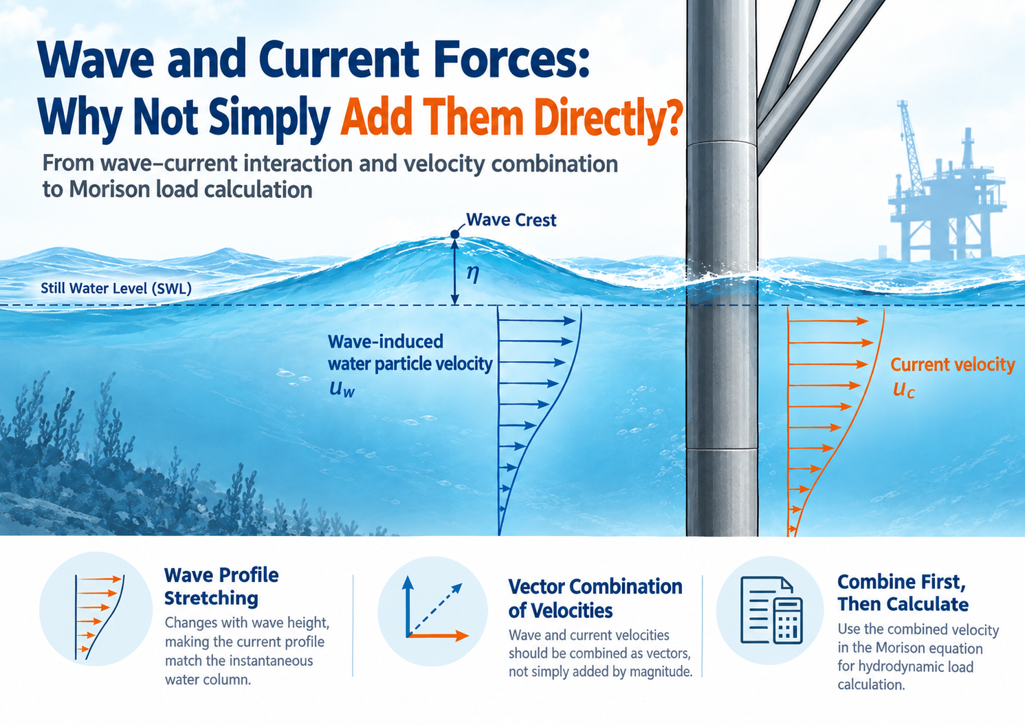
Wave and Current Load Combination: Why Can’t They Simply Be Added?
Wave and current loading should not be treated simply as two independent loads that are calculated separately and then added together. In offshore structural analysis, the correct approach is to first determine the local water-particle motion caused by waves and currents at the same position and time, combine their velocity components in a consistent coordinate system, and then calculate the resulting hydrodynamic force.
This distinction becomes particularly important for offshore structures exposed to large waves, strong currents, and complex current profiles. It can significantly affect the calculated drag force, especially when the Morison equation is used for slender tubular members.
This article explains the engineering principles behind wave-current interaction, current profile stretching, velocity vector combination, Morison drag force, and wave-current load modeling in SACS.
1. Why Wave and Current Loads Cannot Always Be Added Directly
A common approach in offshore structural analysis is to calculate wave loads and current loads independently and then add the resulting forces together.
However, this does not necessarily represent the actual hydrodynamic loading on a structure.
The fundamental question is:
What is the actual water velocity around the structural member at the same location and at the same instant?
The wave-induced velocity and the current velocity exist simultaneously in the water. Therefore, the local water velocity should first be established by combining their velocity vectors. The resulting velocity is then used to calculate the hydrodynamic force.
This is especially important for the drag component of the Morison equation, because drag force is proportional to the square of the relative velocity.
Therefore:
Combining the environmental velocities first and then calculating the hydrodynamic force is not generally equivalent to calculating wave and current forces independently and adding the results afterward.
2. Where Does the Current Come From Above the Still Water Level?
Consider an offshore structure located in a storm condition where:
- Still water level is defined as z = 0
- Water depth is 80 m
- The input current profile is defined only up to the still water level
- The wave crest reaches η = +8 m
When the wave crest passes the structure, the instantaneous free surface rises to +8 m.
A structural member located at z = +4 m is therefore temporarily submerged.
But the original current profile does not directly provide a current velocity at +4 m because the original profile was defined only up to the still water level.
The engineering problem is therefore not to determine the current above the wave crest. Instead, it is to determine the current velocity in the region that is:
above the still water level but below the instantaneous wave surface.
One engineering approach is to transform the current profile according to the instantaneous free-surface elevation. The current profile is effectively stretched or compressed so that:
- The seabed remains associated with the seabed
- The instantaneous wave surface corresponds to the upper boundary of the original current profile
This provides a consistent current velocity distribution throughout the instantaneous wetted region.
3. Current Profile Stretching: Mapping the Local Elevation
Current profile stretching should not be interpreted as simply multiplying every current velocity by a scaling factor.
The key operation is to map the current structural elevation to a corresponding reference elevation in the original current profile, and then obtain the current velocity from that mapped position.
For a simplified linear stretching approach, the relationship can be expressed as:
z’ = -d + (z + d) × d / (d + η)
where:
- d = storm water depth
- η = instantaneous wave elevation
- z = current elevation at the structural location
- z’ = mapped elevation in the original current profile
The same vertical reference system should be used for z, z’ and η, with positive values upward.
For example, assume:
- Water depth: d = 80 m
- Wave elevation: η = +8 m
The mapping can be illustrated as follows:
| Current elevation z | Reference elevation z’ | Current profile interpretation |
|---|---|---|
| −80 m | −80 m | Seabed remains at the bottom of the original profile |
| +4 m | approximately −3.64 m | Take the current velocity from approximately 3.64 m below the original water level |
| +8 m | 0 m | Instantaneous wave surface corresponds to the top of the original profile |
This means that the current velocity at z = +4 m is obtained by evaluating the original current profile at approximately z’ = −3.64 m.
Example of Current Velocity Interpolation
Suppose the original current profile has:
- Current velocity at z = 0 m: 1.5 m/s
- Current velocity at z = −20 m: 1.2 m/s
If linear interpolation is used, the mapped velocity at approximately −3.64 m can be obtained from these two values.
The important point is:
The stretching changes the position from which the current velocity is obtained. It does not simply multiply all current velocities by 88/80.
This distinction is essential when interpreting current profile transformations in offshore hydrodynamic analysis.
4. Linear vs. Nonlinear Current Profile Stretching
Current profile stretching is not necessarily limited to one mathematical method.
API RP 2A-WSD, 22nd Edition, Section 5.3.1.2.6 identifies nonlinear stretching as the preferred method under the conditions described by the standard, while also discussing approximate approaches for particular current-profile characteristics.
For a relatively thick surface slab with an approximately uniform velocity distribution, simple vertical extension can provide a reasonable approximation to nonlinear stretching.
For other types of current profiles, linear stretching may also be used as an engineering approximation, depending on the applicable conditions and analysis methodology.
Therefore, two conclusions should be avoided:
- It is not correct to assume that every current profile can simply be extended upward without consideration.
- It is also not correct to assume that linear stretching is universally unacceptable.
The selection should be based on the characteristics of the current profile, the applicable design standard, and the analysis requirements.
Current Profile vs. Wave Kinematics
Another important distinction is that current profile stretching and wave kinematics are not the same physical process.
Current stretching determines how the current velocity profile is mapped into the instantaneous wetted region.
Methods such as Wheeler stretching are associated with the treatment of wave kinematics.
Although similar elevation-mapping concepts may appear in different formulations, they should not automatically be interpreted as the same software setting or the same physical correction.
5. Wave and Current Velocities Must Be Combined as Vectors
Once the local current velocity has been determined, it can be combined with the wave-induced velocity.
However, the velocities should be combined as vectors, rather than simply adding their magnitudes.
For example, at a particular point and time:
- Wave velocity = 3 m/s toward the east
- Current velocity = 1 m/s toward the north
The resultant horizontal velocity is:
U = √(3² + 1²) ≈ 3.16 m/s
It is therefore not 4 m/s.
If the wave and current velocities are collinear and in the same direction, their signed velocities can be added directly.
For example:
3 m/s + 1 m/s = 4 m/s
But when the directions differ, vector addition is required.
6. The Relevant Velocity for a Structural Member Is the Normal Component
For offshore tubular structures, another important consideration is the direction of the hydrodynamic force relative to the member.
The velocity used for the drag component should generally be considered in relation to the component of flow normal to the structural member.
This means that the magnitude of the overall environmental velocity should not automatically be applied to every inclined or differently oriented tubular member.
For a member with an arbitrary orientation:
- Determine the local wave velocity.
- Determine the local current velocity.
- Combine them in a consistent coordinate system.
- Determine the relative flow velocity.
- Resolve the velocity into the component normal to the member.
- Apply the appropriate hydrodynamic formulation.
If the structural member itself is moving, the relevant quantity also needs to account for the relative velocity between the water and the member.
7. Why the Difference Becomes Significant in the Morison Drag Term
The importance of correctly combining wave and current velocities becomes clearer when examining the Morison equation.
For a fixed circular cylinder subjected to one-dimensional transverse flow, the drag force per unit length can be expressed in simplified form as:
Fᴅ = ½ ρ Cᴅ D U |U|
where:
- Fᴅ = drag force per unit length
- ρ = water density
- Cᴅ = drag coefficient
- D = member diameter
- U = signed relative flow velocity normal to the member
The important feature is the term:
U |U|
Therefore, drag force is nonlinear with respect to velocity.
8. Example: Separate Wave and Current Loads vs. Combined Velocity
Consider a simplified case where:
- Wave velocity = 3 m/s
- Current velocity = 1 m/s
- Both act in the same direction
If the wave and current drag forces are calculated separately and then added, the velocity-square terms are:
3² + 1² = 10
If the velocities are first combined and the drag force is then calculated:
(3 + 1)² = 16
The difference comes from the cross term:
2 × 3 × 1 = 6
The values 10 and 16 are velocity-squared terms, with units of m²/s². They are not forces in kN and do not represent the total hydrodynamic load by themselves.
This simplified example demonstrates why:
Calculating wave and current drag independently and then adding the results is not generally equivalent to calculating drag from the combined local velocity.
The difference is particularly significant when wave and current velocities are large and act in the same direction.
9. What Happens When Wave and Current Act in Opposite Directions?
The same principle applies when wave and current velocities act in opposite directions, but the signed velocity must be retained.
For example:
- Wave velocity = +3 m/s
- Current velocity = −1 m/s
The combined velocity is:
U = +3 − 1 = +2 m/s
The corresponding velocity-squared drag term is based on:
U |U| = 2 × 2 = 4
This illustrates why it is not correct to conclude that separate calculation will always produce a smaller load.
Depending on the relative direction and phase of the wave and current velocities, the difference can change in magnitude and direction.
10. The Morison Equation Also Includes an Inertia Term
The simplified example above focuses only on the drag component.
A complete Morison formulation also contains an inertia term associated with water-particle acceleration.
Therefore, the complete wave-current hydrodynamic load cannot be represented simply by saying that the entire load is proportional to velocity squared.
The drag component demonstrates the nonlinear effect most clearly, while the inertia component must be treated according to the applicable hydrodynamic formulation and wave kinematics.
This distinction is important when interpreting offshore structural analysis results.
11. Wave-Current Interaction in SACS: What Should Engineers Check?
When modeling wave and current effects in SACS, the engineer should look beyond the name of the load case.
A load case called “Wave + Current” does not by itself prove that the underlying physical process has been modeled correctly.
Several aspects should be checked:
1. Water Level Reference
Make sure the following are consistently defined:
- Still water level
- Storm water level
- Wave elevation
- Structural elevations
- Current-profile reference elevations
An inconsistent vertical reference can result in incorrect current mapping.
2. Current Profile Stretching
Check whether the current profile is:
- Stretched
- Extended
- Interpolated
- Modified by another transformation
The selected method should be consistent with the applicable design methodology.
3. Wave Kinematics
Check how the software generates wave-particle velocity and acceleration.
Current-profile transformation and wave-kinematic stretching should not automatically be treated as the same process.
4. Wave-Current Direction
Check the relative angle between wave propagation and current direction.
For non-collinear wave and current conditions, both directional components may affect the analysis.
5. Member Normal Velocity
For each structural member, verify that the appropriate flow component relative to the member orientation is being used.
6. Relative Velocity
If structural motion is relevant, verify whether the hydrodynamic formulation uses the appropriate water-to-member relative velocity.
7. Drag and Inertia Components
Review the separate contributions of:
- Drag force
- Inertia force
- Total hydrodynamic force
Do not interpret the drag-only example as representing the complete Morison load.
12. Apparent Wave Period and Current Velocity Should Not Be Confused
Another important issue in offshore analysis is the current velocity used for estimating apparent wave period.
The current used for this purpose is not necessarily identical to a current value that has already been modified for structural blockage or local effects.
Under the API methodology discussed above, the apparent wave period should be evaluated using the undisturbed free-stream current, rather than a current that has already been reduced by structural blockage.
For non-collinear wave and current conditions, the current component along the wave direction is relevant to apparent wave-period estimation.
At the same time, the current profile used in the hydrodynamic load calculation may require appropriate profile mapping and directional treatment.
Therefore:
A current value modified for one analysis purpose should not automatically be reused for every other calculation step.
13. Structural Load Superposition Is Not the Same as Environmental Load Generation
A critical concept in offshore structural analysis is the difference between load generation and structural response superposition.
Under appropriate linear structural conditions, structural responses may be superposed.
However, this does not mean that the environmental hydrodynamic forces that generated those responses can always be calculated independently and then linearly added.
For example:
Wave velocity + current velocity → local combined velocity → hydrodynamic force → structural response
is fundamentally different from:
Wave force + current force → structural response
when the hydrodynamic force itself is nonlinear with respect to velocity.
This distinction is especially important for Morison drag loading.
14. A Practical Workflow for Wave-Current Load Analysis
A practical engineering workflow can therefore be summarized as follows:
Step 1 — Establish the Water Level
Define the relevant still-water or storm-water reference level and ensure that all elevations use the same datum.
Step 2 — Define the Wave Surface
Determine the instantaneous wave elevation at the location and phase being evaluated.
Step 3 — Map the Current Profile
Determine the current velocity corresponding to the instantaneous wetted elevation using the applicable current-profile transformation.
Step 4 — Determine Wave Kinematics
Calculate the local wave-induced velocity and acceleration at the same location and phase.
Step 5 — Combine Wave and Current Velocities
Perform vector addition in a consistent coordinate system.
Step 6 — Determine Relative Flow
Account for member orientation and, where applicable, structural motion.
Step 7 — Calculate Hydrodynamic Force
Apply the appropriate Morison or other hydrodynamic formulation.
Step 8 — Check Directional Components
Verify that the correct normal and tangential velocity components have been used for each structural member.
Step 9 — Review SACS Output
Check the underlying assumptions and output quantities rather than relying only on load-case names.
Step 10 — Validate Against the Applicable Standard
Review the relevant API requirements, project specifications, software documentation, and analysis assumptions.
15. Key Takeaways
The correct treatment of wave and current loading is fundamentally a water-kinematics problem before it becomes a structural-load problem.
The key principles are:
- Wave and current velocities should be evaluated at the same location and time.
- Current profiles may need to be transformed when the instantaneous free surface differs from the reference water level.
- Current profile stretching changes the velocity sampling position; it is not simply a uniform velocity multiplier.
- Wave and current velocities should be combined as vectors.
- The velocity component normal to the structural member is important for Morison drag.
- Relative water-to-member velocity should be considered when structural motion is relevant.
- Morison drag is nonlinear because it depends on U|U|.
- Calculating wave and current drag separately and adding the results is generally not equivalent to calculating drag from the combined velocity.
- The Morison inertia term requires separate consideration and is not represented by the simple velocity-squared example.
- Current values used for apparent-period estimation should not automatically be confused with blocked or otherwise modified current values used elsewhere.
- Structural response superposition does not imply that environmental hydrodynamic loads can always be generated independently and added linearly.
- SACS load-case names alone are not sufficient to verify the physical correctness of a wave-current analysis.
Conclusion
The key issue in wave-current load combination is not simply whether two forces can be added.
The more fundamental question is:
How is the water actually moving around the structural member at the same position and at the same instant?
Current-profile stretching determines where the current velocity should be obtained.
Vector combination determines how wave and current velocities interact.
The Morison equation determines how the resulting water motion is converted into hydrodynamic force.
These steps are physically connected and, in general, cannot be replaced simply by adding two independently calculated environmental load results.
For reliable offshore structural analysis, engineers should therefore review the complete chain:
Water level → Current profile → Wave kinematics → Wave-current velocity combination → Relative member velocity → Hydrodynamic force → Structural response
This approach provides a more physically consistent basis for analyzing offshore tubular structures subjected to combined wave and current loading.
Frequently Asked Questions
Can wave and current loads simply be added together?
Not in all cases. For Morison drag loading, wave and current velocities should generally be combined before calculating the hydrodynamic drag because the drag force depends nonlinearly on velocity.
What is current profile stretching?
Current profile stretching is a method of mapping the original current velocity profile to the instantaneous wetted water column when the free-surface elevation changes because of waves.
Does current stretching mean multiplying velocity by a scale factor?
No. In general, stretching changes the elevation at which the current velocity is obtained from the original profile. It should not be interpreted simply as multiplying every velocity by a common factor.
What is the difference between wave kinematics and current-profile stretching?
Wave kinematics describe the velocity and acceleration associated with wave motion. Current-profile stretching modifies how a specified current profile is represented within the instantaneous water column. They are related to different physical processes.
Why does the Morison drag force change significantly when wave and current are combined?
Because the drag term depends on the signed relative velocity through U|U|. Therefore, the combined velocity can produce cross terms that are not present when wave and current drag forces are calculated independently.
Does the direction of wave and current matter?
Yes. Wave and current velocities should be treated as vectors. Their relative direction affects the resulting velocity and therefore the hydrodynamic force.
Should the total water velocity be used for every structural member?
Not necessarily. For slender tubular members, the velocity component normal to the member is particularly relevant to transverse drag. Member orientation must therefore be considered.
Can SACS automatically handle wave and current interaction?
The exact treatment depends on the SACS version, analysis settings, input definitions, and selected methodology. Engineers should verify the relevant software documentation and output rather than relying solely on the name of a load case.
Is wave-current load combination the same as structural load superposition?
No. Structural response may be superposed under appropriate linear assumptions, but hydrodynamic force generation can be nonlinear. Therefore, environmental load generation and structural response superposition should be treated as separate concepts.
Post time: Sep-30-2026